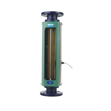
The Difference Between Glass Rotameter And Metal Tube Float Flowmeter
Dec 19, 2021
There are many types of flowmeters. For users, which flowmeter to choose, how to distinguish flowmeter types, characteristics of flowmeters, advantages and disadvantages of flowmeters, etc. The glass rotor flowmeter is the most commonly used type of flowmeter. It has the advantages of reliable performance, low pressure loss, low price, simple structure, and convenient installation and use. According to the purpose and scope of application, it can be divided into eight series: ordinary type, ribbed vascular type, small flow and small shape type, corrosion-resistant type, laboratory type, heat preservation type, alarm type and high pressure resistant type.
The metal tube float flowmeter is a variable area flow measuring instrument commonly used in industrial automation process control. It has the characteristics of small size, large detection range, and convenient use. It can be used to measure the flow of liquid, gas and steam, and is especially suitable for medium flow with low flow rate and small flow.
So what is the difference between a glass rotameter and a metal tube float flowmeter? After all, the measuring tube of the glass rotameter is a glass tube. The glass tube is fragile and cannot withstand excessive pressure. The metal tube float flowmeter adopts a solid all-metal structure, which is suitable for high temperature, high pressure and strong corrosiveness. medium. Another significant difference is that the glass rotor flowmeter generally does not have an output, while the metal tube float flowmeter has an output.
Technical requirements for glass rotameter
1. Before installation, take out the ejector rods and fillers for transportation and protection of the flowmeter.
2. The flowmeter should be installed vertically on a vibration-free pipeline, and no obvious tilt is allowed.
3. The inlet connector of the flow meter should be connected to the small end of its cone.
4. When installing the flowmeter, the pipe fittings connected to the flowmeter must be firmly fixed, and the glass tube should not be stressed.
5. The verification medium should be clean, and if necessary, install a filter upstream of the flowmeter.
6. When the flowmeter installed on the pipeline needs to be cleaned, the cleaning pipeline can be installed.
7. When calibrating the gas flowmeter, a thermometer and pressure gauge should be installed near the inlet of the flowmeter. The minimum division value of the thermometer should not exceed 0.2℃, and the measurement accuracy of the pressure gauge should be within ±1%.
8. The flow standard device must be periodically verified and accompanied by a verification certificate.
9. Dynamic or static flow meter standard device can be selected, and the accuracy of the flow standard device should be at least 1/2 of the allowable error of the flow meter.
10. For flowmeters whose indications are easily affected by changes in liquid viscosity, verification should be carried out as far as possible under the actual working conditions of the flowmeter.
11. The nameplate of the flowmeter should be marked with the name of the manufacturer (or factory standard), the name, model, factory number and date of manufacture of the flowmeter; the tapered tube (or on the certificate) should be marked with the calibration medium and the temperature and pressure of the medium .
12. The reading line of the flowmeter should be clear. The scale of the flowmeter should indicate whether it is a percent scale or a flow scale. The scale flow Q1 of the flowmeter should generally be the flow rate at a temperature of 20°C for liquids; for gas, it should be the flow rate at a standard state (temperature of 20°C and atmospheric pressure of 1.01325×10⁵Pa).
13. The verification system should have good airtightness to ensure no leakage.